mirror of
https://github.com/MOSH-Insa-Toulouse/5ISS-2024-2025-MARIN--MULLER-BOUJON.git
synced 2025-06-08 14:00:49 +02:00
| .. | ||
| img | ||
| .gitignore | ||
| Draft1.asc | ||
| Draft2.asc | ||
| gazgazgaz.asc | ||
| gazgazgaz.asy | ||
| README.md | ||
Hardware
LTSpice simulation
By modifying the R_{cal1} resistor we can see that the maximum output voltage can go up to 5V. The goal would be to modify this resistor value to have a maximum output of around 3.3V:
a=\frac{\Delta{y}}{\Delta{x}}=\frac{y_2-y_1}{x_2-x_1}AN: a=\frac{10k-1k}{2.1-4.94}AN: a=-3170y=-3170x+b1000=-3170(4.94)+bb=3170(4.94)+1000b=16659y=-3170x+16659We can now calculate the resistor R_{cal1} to have 3.3V in maximum output with the previous formula, we find:
-3.17\times{10^3\times{3.3V}}+16.7\times{10^3}=6.2k\Omega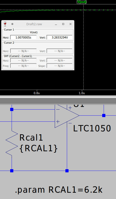
Has we can see with the LTSpice simulation, we have the correct maximum voltage, it does not go further than
3.29Vwhich is exactly what we wanted.